

 |
|
 |
 |
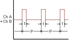
Duty cycle is a measure of ON or OFF period as a percentage of total period. Duty cycle is determined by averaging an integral number of periods over a gate time which is selectable from 10 ms to 199.99 s. The same signal is applied to Channels A and B. The transmitter divides the average pulse width t by the period P between pulses and expresses the ratio t/P in percent. A resolution of 1%, 0.1% or 0.01% is selectable. By selecting leading or falling pulse edges, ON or OFF duty cycle can be transmitted.
Pulse Width Modulation (PWM) is a transducer output format where the measured information is provided as duty cycle applied to a constant frequeny, such as 120 Hz. As for duty cycle, the transmitter divides the average pulse width by the period between pulses over a gate time which is selectable from 10 ms to 199.99 s. It then scales this ratio mathematically to transmit this ratio in engineering units, such as relative humidity (RH).
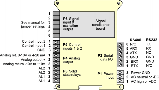
The Laureate duty cycle & pulse width modulation transmitter uses an Extended counter transmitter main board and the FR dual-channel signal conditioner board, which accepts signals from 12 mV to 250 Vac, inputs from proximity switches with an PNP or NPN output, TTL or CMOS logic, and contact closures. Jumper selections provide optimum operation for different sensor types and noise conditions. A built-in isolated 5, 10, or 24 Vdc excitation supply can power proximity switches and other sensors.
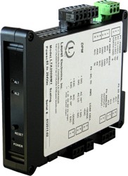
Standard features of Laureate LT transmitters include:
Transmitter programming is via Laurel's Instrument Setup Software, which runs on a PC under MS Windows. This software can be downloaded from this website at no charge. The required transmitter-to-PC interface cable is available from Laurel (P/N CBL04).
| Duty Cycle Measurement | |
|---|---|
| Item Transmitted | ON or OFF duty cycle of periodic pulse waveshape |
| Displayed Units | 1%, 0.1%, 0.01% |
| Frequency Range | 0.005 Hz to 10 kHz |
| Accuracy | 0.01%, 0.005 Hz to 500 Hz, 0.1% at 5 kHz, 1% at 10 kHz |
| Maximum Timing Interval | 199.99 s |
| Pulse Width Modulation (PWM) Measurement | |
| Item Transmitted | Measurement based on Pulse Width Modulation (PWM) input |
| Displayed Units | Scaled reading in engineering units |
| Frequency Range | 0.005 Hz to 10 kHz |
| Accuracy | 0.01%, 0.005 Hz to 500 Hz, 0.1% at 5 kHz, 1% at 10 kHz |
| Maximum Timing Interval | 199.99 s |
| Update Rate | |
| Conversion Interval | Gate time + 30 ms + 0-2 signal periods |
| Gate Time | Selectable 10 ms to 199.99 s |
| Time Before Zero Output | Selectable 10 ms to 199.99 s |
| Pulse Input | |
| Types | AC, pulses from NPN, PNP transistors, contact closures, magnetic pickups |
| Grounding | Common ground for channels A & B. |
| Minimum Signal | Nine ranges from (-12 to +12 mV) to (+1.25 to +2.1V) |
| Maximum Signal | 250 Vac |
| Noise Filter | 1 MHz, 30 kHz, 250 Hz (selectable) |
| Contact Debounce | 0, 3, 50 ms (selectable) |
| Analog Output (standard) | |
| Output Levels | 4-20 mA, 0-20 mA, 0-10 Vdc, -10 to +10Vdc (user selectable) |
| Compliance at 20 mA | 10V (0-500Ω load) |
| Compliance at 10V | 2 mA (5 kΩ load) |
| Output Resolution | 16 bits (65,536 steps) |
| Output Accuracy | 0.02% of output span plus conversion accuracy |
| Output Isolation | 250V rms working, 2.3 kV rms per 1 minute test |
| Serial Data Output (standard) | |
| Signal Types | RS232 or RS485 (half or full duplex), jumper selectable |
| Data Rates | 300, 600, 1200, 2400, 4800, 9600, 19200 baud |
| Output Isolation | 250V rms working, 2.3 kV rms per 1 min test |
| Serial Protocols | Modbus RTU, Modbus ASCII, Custom ASCII |
| Modbus Compliance | Modbus over Serial Line Specification V1.0 (2002) |
| RS232/RS485 Connector | Screw terminals for easy daisy chaining |
| Digital Addresses | 247 for Modbus, 31 for Custom ASCII |
| Dual Relay Output (standard) | |
| Relay Type | Two solid state relays, SPST, normally open, Form A |
| Load Rating | 120 mA at 140 Vac or 180 Vdc |
| Sensor Excitation Output (standard) | |
| Output Levels | 5V@100 mA, 10V@120 mA, 24V@50 mA (jumper selectable) |
| Output Isolation | 50V from signal ground |
| Power Input | |
| Standard Power | 85-264 Vac or 90-300 Vdc |
| Low Power Option | 10-48 Vdc or 12-32 Vac |
| Power Frequency | DC or 47-63 Hz |
| Power Isolation | 250V rms working, 2.3 kV rms per 1 min test |
| Power Consumption at 24V | 1.5W typical, 3W with max excitation output |
| Mechanical | |
| Dimensions | 129 x 104 x 22.5 mm case |
| Mounting | 35 mm rail per DIN EN 50022 |
| Electrical Connections | Plug-in screw-clamp connectors |
| Environmental | |
| Operating Temperature | 0°C to 55°C |
| Storage Temperature | -40°C to 85°C |
| Relative Humidity | 95% at 40°C, non-condensing |
| Cooling Required | Mount transmitters with ventilation holes at top and bottom. Leave 6 mm (1/4") between transmitters, or force air with a fan. |
| Duty Cycle & Pulse Width Modulation (PWM) Modes | |
|---|---|
 |
In duty cycle mode, the transmitter displays ON or OFF time in percent from 0% to 100% of period for repetitive pulse trains. In the illustration, duty cycle in percent is 100 x t/P. In pulse width modulation (PWM) mode, the meter also determines the duty cycle ratio, but then scales this ratio for display in engineering units. |
 |
|
|||||||||
| © 1990-2024 Laurel Electronics | ||||||||||


